
last edited: 2026-07-10 00:03:14 +0000
Ruby
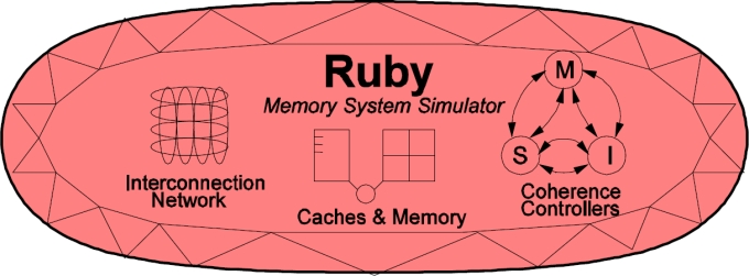
Ruby implements a detailed simulation model for the memory subsystem. It models inclusive/exclusive cache hierarchies with various replacement policies, coherence protocol implementations, interconnection networks, DMA and memory controllers, various sequencers that initiate memory requests and handle responses. The models are modular, flexible and highly configurable. Three key aspects of these models are:
- Separation of concerns – for example, the coherence protocol specifications are separate from the replacement policies and cache index mapping, the network topology is specified separately from the implementation.
- Rich configurability – almost any aspect affecting the memory hierarchy functionality and timing can be controlled.
- Rapid prototyping – a high-level specification language, SLICC, is used to specify functionality of various controllers.
The following picture, taken from the GEMS tutorial in ISCA 2005, shows
a high-level view of the main components in Ruby.
For a tutorial-based approach to Ruby see Part III of Learning gem5
SLICC + Coherence protocols:
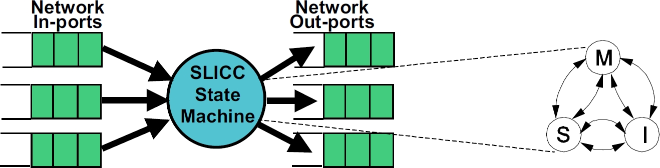
SLICC stands for Specification Language for Implementing Cache Coherence. It is a domain specific language that is used for specifying cache coherence protocols. In essence, a cache coherence protocol behaves like a state machine. SLICC is used for specifying the behavior of the state machine. Since the aim is to model the hardware as close as possible, SLICC imposes constraints on the state machines that can be specified. For example, SLICC can impose restrictions on the number of transitions that can take place in a single cycle. Apart from protocol specification, SLICC also combines together some of the components in the memory model. As can be seen in the following picture, the state machine takes its input from the input ports of the inter-connection network and queues the output at the output ports of the network, thus tying together the cache / memory controllers with the inter-connection network itself.
The following cache coherence protocols are supported:
- MI_example: example protocol, 1-level cache.
- MESI_Two_Level: single chip, 2-level caches, strictly-inclusive hierarchy.
- MOESI_CMP_directory: multiple chips, 2-level caches, non-inclusive (neither strictly inclusive nor exclusive) hierarchy.
- MOESI_CMP_token: 2-level caches. TODO.
- MOESI_hammer: single chip, 2-level private caches, strictly-exclusive hierarchy.
- Garnet_standalone: protocol to run the Garnet network in a standalone manner.
- MESI Three Level: 3-level caches, strictly-inclusive hierarchy. Based on MESI Two Level with an extra L0 cache.
- CHI: flexible protocol that implements Arm’s AMBA5 CHI transactions. Supports configurable cache hierarchy with both MESI or MOESI coherency.
Commonly used notations and data structures in the protocols have been described in detail here.
Protocol independent memory components
- Sequencer
- Cache Memory
- Replacement Policies
- Memory Controller
In general cache coherence protocol independent components comprises of the Sequencer, Cache Memory structure, Cache Replacement policies and the Memory controller. The Sequencer class is responsible for feeding the memory subsystem (including the caches and the off-chip memory) with load/store/atomic memory requests from the processor. Every memory request when completed by the memory subsystem also send back the response to the processor via the Sequencer. There is one Sequencer for each hardware thread (or core) simulated in the system. The Cache Memory models a set-associative cache structure with parameterizable size, associativity, replacement policy. L1, L2, L3 caches (if exists)in the system are instances of Cache Memory. The Cache Replacement policies are kept modular from the Cache Memory, so that different instances of Cache Memory can use different replacement policies of their choice. Currently two replacement polices – LRU and Pseudo-LRU – are distributed with the release. Memory Controller is responsible for simulating and servicing any request that misses on all the on-chip caches of the simulated system. Memory Controller currently simple, but models DRAM ban contention, DRAM refresh faithfully. It also models close-page policy for DRAM buffer.
Interconnection Network
The interconnection network connects the various components of the memory hierarchy (cache, memory, dma controllers) together.

The key components of an interconnection network are:
- Topology
- Routing
- Flow Control
- Router Microarchitecture
More details about the network model implementation are described here.
Alternatively, Interconnection network could be replaced with the external simulator TOPAZ. This simulator is ready to run within gem5 and adds a significant number of features over original ruby network simulator. It includes, new advanced router micro-architectures, new topologies, precision-performance adjustable router models, mechanisms to speed-up network simulation, etc.
Life of a memory request in Ruby
In this section we will provide a high level overview of how a memory request is serviced by Ruby as a whole and what components in Ruby it goes through. For detailed operations within each components though, refer to previous sections describing each component in isolation.
- A memory request from a core or hardware context of gem5 enters the jurisdiction of Ruby through the RubyPort::recvTiming interface (in src/mem/ruby/system/RubyPort.hh/cc). The number of Rubyport instantiation in the simulated system is equal to the number of hardware thread context or cores (in case of non-multithreaded cores). A port from the side of each core is tied to a corresponding RubyPort.
- The memory request arrives as a gem5 packet and RubyPort is responsible for converting it to a RubyRequest object that is understood by various components of Ruby. It also finds out if the request is for some PIO or not and maneuvers the packet to correct PIO. Finally once it has generated the corresponding RubyRequest object and ascertained that the request is a normal memory request (not PIO access), it passes the request to the Sequencer::makeRequest interface of the attached Sequencer object with the port (variable ruby_port holds the pointer to it). Observe that Sequencer class itself is a derived class from the RubyPort class.
- As mentioned in the section describing Sequencer class of Ruby, there are as many objects of Sequencer in a simulated system as the number of hardware thread context (which is also equal to the number of RubyPort object in the system) and there is an one-to-one mapping between the Sequencer objects and the hardware thread context. Once a memory request arrives at the Sequencer::makeRequest, it does various accounting and resource allocation for the request and finally pushes the request to the Ruby’s coherent cache hierarchy for satisfying the request while accounting for the delay in servicing the same. The request is pushed to the Cache hierarchy by enqueueing the request to the mandatory queue after accounting for L1 cache access latency. The mandatory queue (variable name m_mandatory_q_ptr) effectively acts as the interface between the Sequencer and the SLICC generated cache coherence files.
- L1 cache controllers (generated by SLICC according to the coherence protocol specifications) dequeues request from the mandatory queue and looks up the cache, makes necessary coherence state transitions and/or pushes the request to the next level of cache hierarchy as per the requirements. Different controller and components of SLICC generated Ruby code communicates among themselves through instantiations of MessageBuffer class of Ruby (src/mem/ruby/buffers/MessageBuffer.cc/hh) , which can act as ordered or unordered buffer or queues. Also the delays in servicing different steps for satisfying a memory request gets accounted for scheduling enqueue-ing and dequeue-ing operations accordingly. If the requested cache block may be found in L1 caches and with required coherence permissions then the request is satisfied and immediately returned. Otherwise the request is pushed to the next level of cache hierarchy through MessageBuffer. A request can go all the way up to the Ruby’s Memory Controller (also called Directory in many protocols). Once the request get satisfied it is pushed upwards in the hierarchy through MessageBuffers.
- The MessageBuffers also act as entry point of coherence messages to the on-chip interconnect modeled. The MesageBuffers are connected according to the interconnect topology specified. The coherence messages thus travel through this on-chip interconnect accordingly.
- Once the requested cache block is available at L1 cache with desired coherence permissions, the L1 cache controller informs the corresponding Sequencer object by calling its readCallback or ‘writeCallback’’ method depending upon the type of the request. Note that by the time these methods on Sequencer are called the latency of servicing the request has been implicitly accounted for.
- The Sequencer then clears up the accounting information for the corresponding request and then calls the RubyPort::ruby_hit_callback method. This ultimately returns the result of the request to the corresponding port of the core/ hardware context of the frontend (gem5).
Directory Structure
- src/mem/
- protocols: SLICC specification for coherence protocols
- slicc: implementation for SLICC parser and code generator
- ruby
- common: frequently used data structures, e.g. Address (with bit-manipulation methods), histogram, data block
- filters: various Bloom filters (stale code from GEMS)
- network: Interconnect implementation, sample topology specification, network power calculations, message buffers used for connecting controllers
- profiler: Profiling for cache events, memory controller events
- recorder: Cache warmup and access trace recording
- slicc_interface: Message data structure, various mappings (e.g. address to directory node), utility functions (e.g. conversion between address & int, convert address to cache line address)
- structures: Protocol independent memory components – CacheMemory, DirectoryMemory
- system: Glue components – Sequencer, RubyPort, RubySystem