last edited: 2026-07-10 00:03:14 +0000
More details of the gem5 Ruby Interconnection Network are here. Details about the earlier Garnet version can be found here.
HeteroGarnet: A Detailed Simulator for Diverse Interconnect Systems
HeteroGarnet improves upon the widely-popular Garnet 2.0 network model by enabling accurate simulation of emerging interconnect systems. Specifically, HeteroGarnet adds support for clock-domain islands, network crossings supporting multiple frequency domains, and network interface controllers capable of attaching to multiple physical links. It also supports variable bandwidth links and routers by introducing a new configurable Serializer-Deserializer component. HeteroGarnet is integrated into the gem5 repository as Garnet 3.0.
HeteroGarnet builds upon the original Garnet model which was published in 2009.
If your use of HeteroGarnet contributes to a published paper, please cite the following paper:
    @inproceedings{heterogarnet,
        author={Bharadwaj, Srikant and Yin, Jieming and Beckmann, Bradford and Krishna, Tushar},
        booktitle={2020 57th ACM/IEEE Design Automation Conference (DAC)},
        title={Kite: A Family of Heterogeneous Interposer Topologies Enabled via Accurate Interconnect Modeling},
        year={2020},
        volume={},
        number={},
        pages={1-6},
        doi={10.1109/DAC18072.2020.9218539}
	}
Topology Construction
HeteroGarnet allows users to configure complex topologies using a python configuration file as the topology. The overall topology configuration could include the complete interconnect definition of the system including any heterogeneous components. The general flow of defining a topology involves the following steps:
- Determine the total number of routers in the system and instantiate them.
- Use the Router class to instantiate individual routers.
- Configure properties of each router, such as clock domain, supported flit width, depending on the requirements.
routers = Router(id, latency, clock_domain,
         flit_width, supported_vnets,
         vcs_per_vnet)
- Connect the routers which connect to the end points (e.g, Cores, Caches, Directories) using external physical interconnects.
- Use ExternalLink class to instantiate the links connecting the end points.
- Configure properties of each external link, such as clock domain, link width, depending on the requirements.
- Enable clock-domain crossings(CDC) and Serializer-Deserializer(SerDes) units at either depending on the interconnect topology.
external_link = ExternalLink(id, latency, clock_domain,
                      flit_width, supported_vnets,
                      serdes_enable, cdc_enable)
- Connect the individual routers within the network depending upon the topology.
- Use InternalLink class to instantiate the links connecting the end points.
- Configure properties of each internal link, such as clock domain, link width, depending on the requirements.
- Enable clock-domain crossings and Serializer-Deserializer units at either depending on the interconnect topology.
internal_link = InternalLink(id, latency, clock_domain,
                      flit_width, supported_vnets,
                      serdes_enable, cdc_enable)
Garnet 3.0 also provides several pre-configuration scripts(./configs/Network/Network.py) which automatically do some of the other steps, such as instantiating network interfaces, domain crossings, and SerDes units. The several types of units used to configure the topologies are discussed below.
Physical Links
The physical link model in Garnet represents the interconnect wire itself. A link is a single entity which has its own latency, width and the types of flit it can transmit. The links also support a credit based back-pressuring mechanism. Similar to the upgraded Garnet 3.0 router, each Garnet 3.0 link can be configured to an operating frequency and width using appropriate parameters. This allows links and routers operating at different frequencies to be connected to each other.
Network Interface
The network interface controller (NIC) is an object which sits between the network end points (e.g., Caches, DMA nodes) and the interconnection system. The NIC receives messages form the controllers and converts them into fixed-length flits, short for flow control units. These flits are sized appropriately according to the outgoing physical links. The network interface also governs the flow control and buffer management for the outgoing and incoming flits. Garnet 3.0 allows multiple ports to be attached to a single end points. Thus, the NIC decides where a certain message/flit must be scheduled.
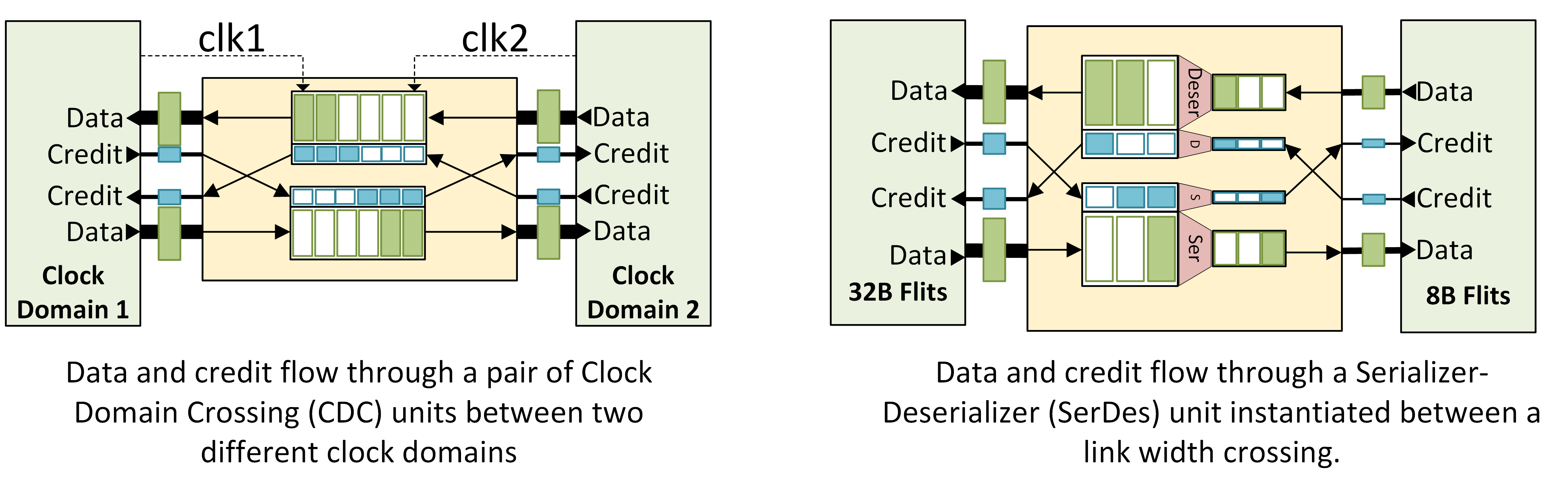
Clock Domain Crossing Units
To support multiple clock domains, Garnet 3.0 introduces Clock Domain Crossing (CDC) unit, as shown in the Figure below (left), which consists of first-In-First-Out (FIFO) buffers and can be instantiated anywhere within the network model. The CDC unit enables architectures with different clock domains across the system. The delay of each CDC unit configurable. The latency can also be calculated dynamically depending on the clock domains connected to it. This enables accurate modeling of DVFS techniques as CDC latencies are generally a function of the operating frequency of producer and consumer.
Serializer-Deserializer Units
Another critical feature necessary in modeling SoCs and heterogeneous architectures is supporting various interconnect widths across the system. Consider a link between two routers within a GPU and a link between a memory controller and on-chip memory. These two links might be of different widths. To enable such configuration, Garnet 3.0 introduces the Serializer-Deserializer unit as shown in the figure below, which converts flits into appropriate widths at bit-width boundaries. These SerDes units can be instantiated anywhere in the Garnet 3.0 topology similar to the CDC unit described in the previous sub-section.
Routing
The routing algorithm decides how the flits travel through the topology. The objective of a routing policy is to minimize contention while maximizing the bandwidth offered by the interconnect. Garnet 3.0 provides several standard routing policies that the user can select from.
Routing Policies.
There are several generic routing policies that have been proposed for deadlock free routing of flits through the interconnect network.
Table based routing
Garnet also features table based routing policy which users can select to set custom routing policies using a weight-age based system. Lower weighted links are preferred over links which are configured to have higher weights.
Flow Control and Buffer Management
Flow control mechanisms determine the buffer allocation in interconnect systems. The aim of a good flow control system is minimize the impact of buffer allocation to the overall latency of a message in the system. Implementation of these mechanisms often involve micro-management of physical packets within the interconnect system.
Coherence messages generated by cache controllers are often broken down into fixed-length flits (flow control units). A set of flits carrying a message is often termed as a packet. A packet could have a head-flit, body-flit, and a tail-flit to carry the contents of the message along with any additional meta data of the packet itself. Several flow control techniques have been proposed and implemented at various granularities of resource allocation.
Garnet 3.0 implements a credit-based flit-level flow control mechanism with support for virtual channels.
Virtual Channels
Virtual Channels (VCs) in a network act as separate queues which can share physical wires (physical links) between two routers or arbiters. Virtual channels are mainly used to alleviate head-of-line blocking. However, they are also used as a means for deadlock-avoidance.
Buffer Backpressure
Most implementations of interconnection networks do not tolerate dropping of packets or flits during traversal. Thus, there is a need to strictly manage the flits using backpressuring mechanisms.
Credit-based backpressuring
Credit-based backpressuring mechanism is often used for low-latency implementation of flit-stalling. Credits track the number of buffers available at the next intermediate destination by decrementing the overall buffers every time a flit is sent. A credit is then sent back by the destination when it is vacated.
Routers in interconnect systems perform arbitration, allocation of buffers, and flow control within the network. The objective of the router microarchitecture is to minimize the contention within the router while offering minimal per-hop latency for the flits. The complexity of the router microarchitecture also affects the overall energy and area consumption of the interconnect system.
Life of a Message in Garnet 3.0
In this section we describe the life of a message in the NoC after it is generated by a cache controller unit. We take the case of Garnet 3.0 for describing the process, but the general modeling principles can be extended to other software simulation/modeling tools as well.
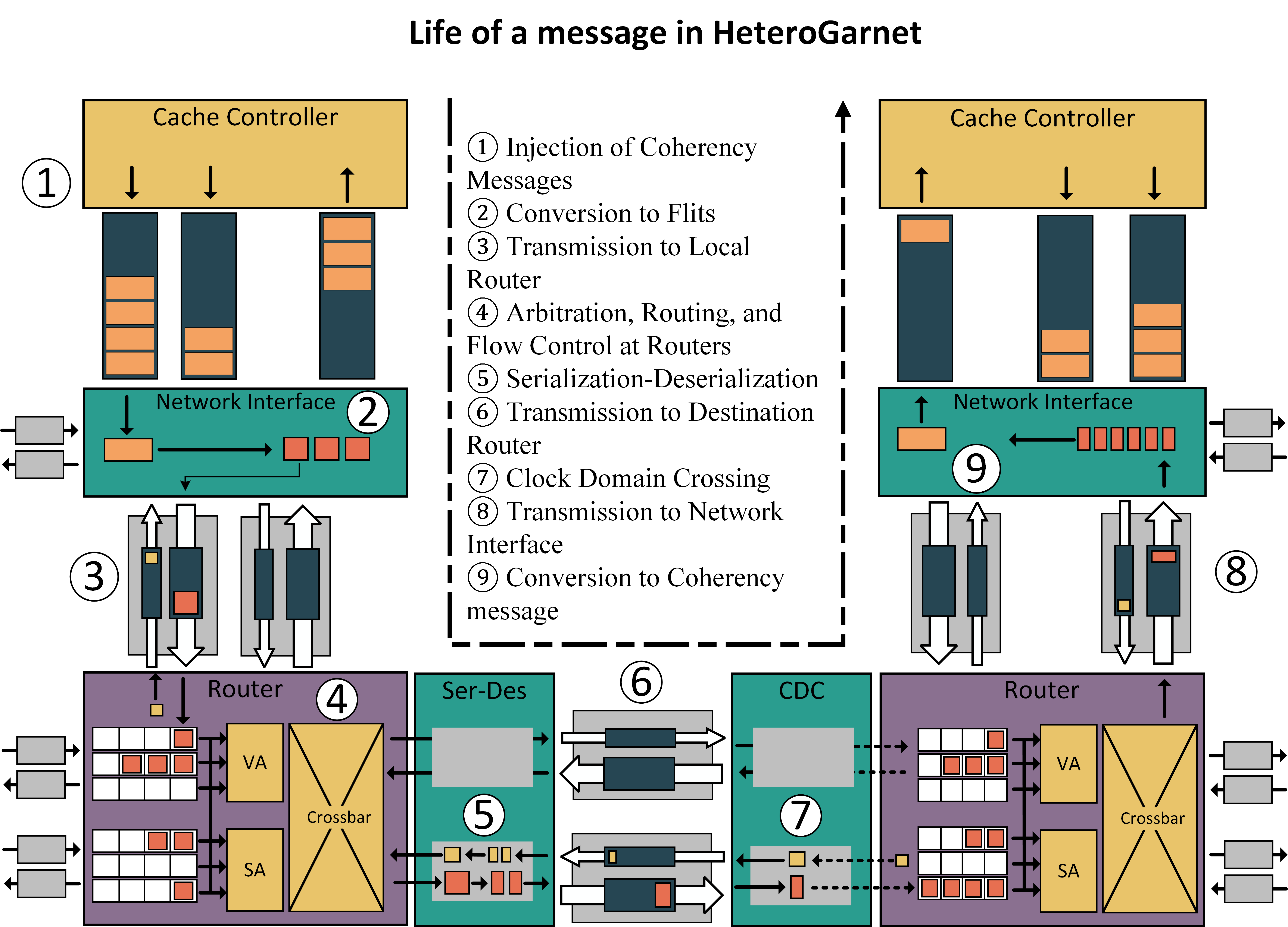
The overall flow of the system is shown in detail in figure above. It shows a simple example scenario where a message is generated by a cache controller destined for another cache controller which is connected through routers via physical links, serializer-deserializer units, and clock-domain crossings.
Injection of Message
The source cache controller creates a message and assigns one or more cache controllers as the destination. This message is then injected into message queues. A cache controller often has several outgoing and incoming message buffers for different kinds of messages.
Conversion to Flits.
A network interface controller unit (NIC) is attached to each cache controller. This NIC wakes up and consumes the messages from the message queues. Each message is then converted to unicast messages before being broken down into fixed-length flits according to the size supported by the outgoing physical links. These flits are then scheduled for transmission depending on the availability of buffers at the next hop through one of the output links. The outgoing link is chosen depending on the destination, routing policy, and the type of message.
Transmission to Local Router.
Each network interface is connected to one or more “local” routers which is could be connected through an “External” link. Once a flit is scheduled, it is transmitted over these external links which deliver the flit to the router after a period of defined latency.
Router Arbitration.
The flit wakes up the router which is a multi-stage unit. The router houses the input buffers, VC allocation, switch arbitration, and crossbar units. On arrival the flit is first placed in a input buffer queue. There are several input buffer queues in a router which contend for an output link and a VC for the next hop. This is done using the VC allocation and switch arbitration stages. Once a flit is selected for transmission, the crossbar stage directs the flit to the output link. A credit is then sent back to the NIC as the input buffer space is vacated for the next flit to arrive.
Serialization-Deserialization.
The serialization-deserialization (SerDes) is an optional unit that can be enabled depending on the design requirements. The SerDes units consumes the flits and appropriately converts it into outgoing flit size. In addition to manipulating the data packets, the SerDes also handles the credit system, by serializing or deserializing the credit units.
Area, Power and Energy Model
Frameworks like Orion2.0 and DSENT provide models for the area and power for the various building blocks of a NoC router and links. HeteroGarnet integrates DSENT as an external tool to report area, power and energy (which depends on activity) at the end of the simulation.